KnowledgeECONOMICS
CONTACT US
Hunan Perfect Industry Co.,Ltd
Contact: Manager Hu, Manager Yi
Hotline:008618507312158
Cell phone:008613974960765
Address:Xiangyin County Industrial Park, Yueyang City, Hunan Province, China
Current location: HOME »Knowledge »vertical turbine pump
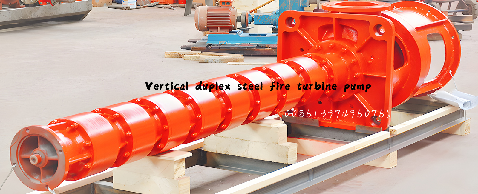
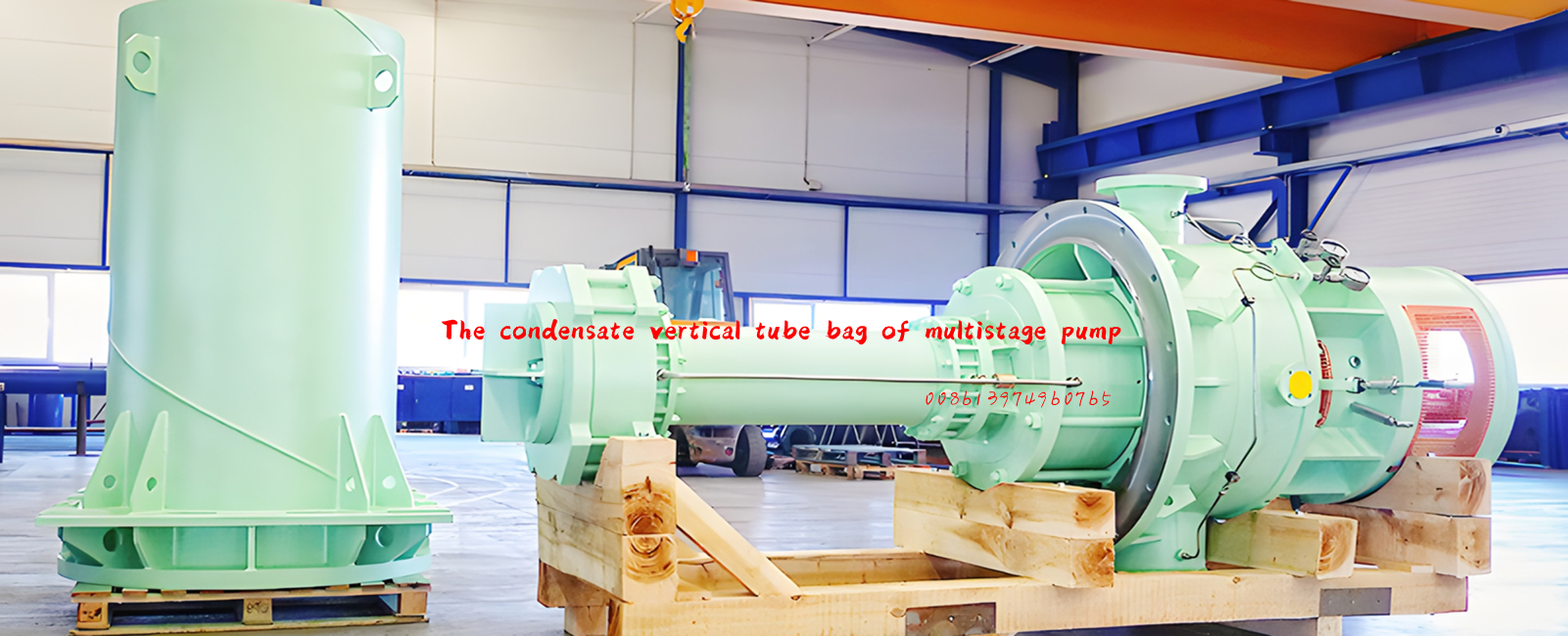
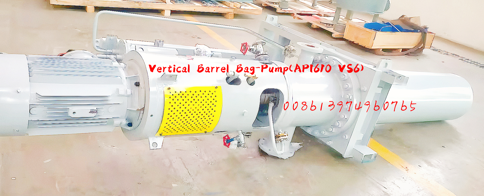
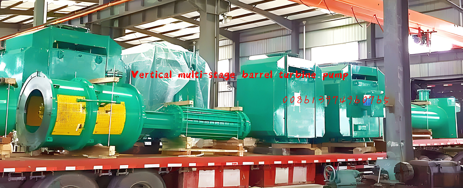
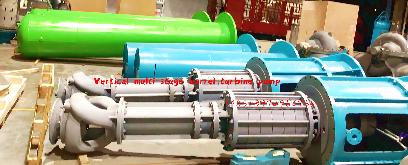
Description and Configuration Of The Canned Vertical Turbine Pump (double casing vertical turbine pumps)
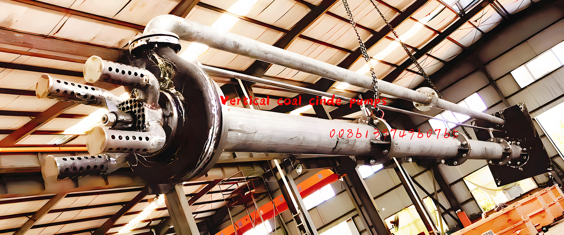
The model LTDN covers the highly engineered specialty end of double casing vertical turbine pumps. The pump line is based on a modular system, thus providing maximum design and operating flexibility. This is combined with specific design features, including stiff shaft construction, a self-contained axial thrust bearing housing and pressure containing parts certified to various international standards. Altogether, this makes the LTDN Canned double casing vertical turbine pump of choice for the most critical applications where space considerations or marginal NPSHA values preclude the use of a horizontal multistage pump.
Liquid is flowing through the suction flange of the headstock and through the Can to the impellers. The last stage impeller is discharging the liquid via the column pipes, to the discharge flange. The thrust is balanced by back wearing rings and balancing holes.
The headstock is equipped with a drain connection, which allows to flush the Can with Nitrogen before disassembly.
A vent connection for the suction is standard. The sense of rotation of the Canned double casing vertical turbine pump is counter clockwise, looking from the coupling to the shaft end of the Canned double casing vertical turbine pump.

Design of major parts
Motor stool
The motor stool supports the thrust bearing. On top the driver is mounted.
Headstock
Headstock has inline suction and discharge nozzle, including all the necessary vent and drain
connections. It is a major part of the Canned double casing vertical turbine pump unit, which supports the column pipes with the hydraulics as well as the motor stool and driver.
Can (also referred as 'barrel')
The Can (also referred as 'barrel') is subjected to suction pressure and guides the fluid to the first stage impeller.
Hydraulics:Radial flow hydraulics,Mixed flow hydraulics
Radial flow hydraulics
This are ring section type hydraulics. Suction, stage and discharge casing are hold together by strong tie bolts, which allows a very compact and short design.
The radial impellers are hydraulically balanced by back wear rings and balancing holes. The diffusers are designed with 7 to 11 vanes to minimize the radial forces at part load operation. All impellers are slipped on the shaft and axially fixed by the impeller nut. The shaft is supported in the suction casing, in every diffuser and in the discharge casing.
Optional the hydraulics can be fitted with an inducer for low NPSH requirement.
Mixed flow hydraulics
The hydraulics consists of flanged bowls and a suction casing. The impellers are hydraulically balanced by back wear rings and balancing holes.
The diffusers are designed with 7 to 11 vanes to minimize the radial forces at part load operation. All impellers are slipped on the shaft and axially fixed by the impeller nut. The shaft is supported in the suction casing and in each bowl.
Optional the hydraulics can be fitted with an inducer for low NPSH requirement.

